Magnetism and Electro-magnetism
Magnetism and basic electricity are so closely related that one cannot be studied at length without involving the other. There are three general relationships that exist between them:
• Current flow will always produce some form of magnetism.
• Magnetism is by far the most commonly used means for producing or using electricity.
• The peculiar behavior of electricity under certain conditions is caused by magnetic influences.
The importance of magnetism plays a key role in circuit protection and control devices. This importance will become apparent as you go through the different modules.
Let's talk about the main source of magnetism, a magnet. Every magnet has three common properties:
1. They attract and hold iron.
2. They all have two poles, one north and one south.
3. They will assume close to a north-south alignment, if permitted to move.
Every magnet is surrounded by a magnetic field that consists of flux lines or lines of force that extend into space from one end of the magnet to the other as well as inside the magnet. The north and south poles attract one another because the poles are opposites. It also holds true that two like poles repel one another.

Even though flux lines are invisible, their effects can be shown by a simple demonstration. When a sheet of paper is placed on a magnet and iron filings are loosely scattered over it, the filings arrange themselves along the flux lines. They leave the north pole and enter the south pole. There are two types of magnets:
Permanent Magnets and
Electromagnets. Permanent magnets retain their magnetism after a magnetizing force has been removed. The interaction of electric current and a magnetic field creates electromagnetism. Electromagnets are similar to permanent magnets, except they do not retain their magnetism when the electricity is removed, and they can be made stronger.
To make a typical electromagnet, take an iron rod and wrap it with insulated wire. The iron rod is called a "core." When the wire is connected to a battery, electric current flows through the wire. This current magnetizes the iron core which creates a north and south pole. When one or both ends of the wire at the battery are disconnected, the current flow stops. The core loses its magnetism.
Changing the direction of the current flow can reverse the poles of an electromagnet. To change the direction, just interchange the wire connections. This is because the battery produces DC voltage, which flows in one direction.
Alternating current changes directions on its own. As the current direction changes, the electromagnet poles change. Unlike the permanent magnet, the direction of the flux lines is not constant. They are related to the direction of current flow through the conductor.
The relationship between current flow and flux lines can be demonstrated using the Right-Hand Rule. A current carrying conductor is held with the right hand and the thumb pointing in the direction of the current flow. Wrap the fingers around the conductor. The fingers point in the direction of the lines of flux.
This right-hand rule is followed when using conventional flow, but when electron flow is used, then the left-hand rule would be used. This rule is the same as right-hand rule except you do everything with your left hand. When we deal with motors in a later module, we will use left-hand rule because of the way motors react with the magnetic flux and current.

Finally, if current in two parallel conductors is flowing in opposite directions, the magnetic fields would also flow in opposite directions, and a natural repulsion is created. The degree of repulsion depends on the magnitude of the current.

These basic electromagnetic principles led to the invention of a wide variety of electrical devices such as the previously mentioned motors, generators, solenoids, tripping devices and circuit breakers.
Alternating Current (AC)
As stated previously, there are two types of voltages: DC and AC. To this point we have been focusing on DC. DC voltage is very simple, straight forward and is created by batteries and DC generators.
Now let's focus on AC voltage. A generator or alternator is used to produce AC voltage. AC is generated by utility companies and transmitted to our homes, factories, stores and offices. AC voltage is used for many reasons, but one of the main reasons is it can be stepped up or down by a
Transformer. This permits the transmission lines to operate at high voltages and low currents for maximum efficiency. The consumer can then step down the voltage to the desired level.
Sine WavesAn AC generator converts mechanical energy into electrical energy. The theory of magnetism is what allows the generator to produce AC voltage. This is because a current carrying conductor produces a magnetic field around itself. A changing magnetic field produces voltage in a conductor. Likewise, if a conductor lies in a magnetic field, and either the field or conductor moves, a voltage is induced in the conductor. This effect is called
Electromagnetic Induction. Below is a simple AC generator with a single loop of wire and a magnetic field for simplicity. The figure shows the loop of wire rotating in a clockwise direction through the magnetic field of the magnets. This will show how a sine wave graphically represents AC voltage and current. The coil will cover a 360-degree rotation and show what happens at different points in the rotation. The rotating coil is divided into black and white halves to keep track of the coil's position.

Step 1: Starting point at 0 degrees
With the coil at 0 degrees and no rotation, no voltage is generated and no portion of the sine wave appears on the horizontal and vertical axes. As the coil rotates from 0 to 90 degrees, it cuts more and more lines of flux. As the lines of flux are cut, voltage is generated in the positive direction.

As the coil continues to rotate, it cuts fewer and fewer lines of flux. Therefore, the voltage generated goes from maximum back to zero.

This is similar to Step 2 except voltage is now generated in the negative direction.

This is similar to Step 3 except the voltage is still negative. Once it reaches 0 degrees, one complete 360-degree revolution has been completed. At this point, the coil is back to its original starting position and one cycle has been completed. If the coil continues to rotate, the cycle will continue to repeat.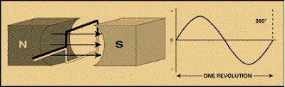 AC goes through many of these cycles each second. The number of cycles per second is called the Frequency. In the U.S., AC is generated of 60 hertz. This means that 60 cycles are completed every second. Frequency will be discussed in more detail in later modules.
Labels:
Electrical Power
 The calculations show us that the 100-watt bulb has less resistance and, therefore, more current flow. This shows that the 100-watt bulb converts electric energy faster, performs more work, gives off more light/heat, and uses more energy.
 The AC sine wave varies constantly in direction (polarity) and magnitude. Usually, the DC wave is considered to be a steady, non-varying, uni-directional wave. The direction (polarity) of an AC wave generally reverses on a cyclical basis, that is, the wave takes on both positive and negative values, alternately.
 Sine Wave Values
 Peak-to-Peak Value: The peak-to-peak value is the value of voltage or current between the positive and negative peaks.
 Effective Value: As would be expected, there are a number of different values of voltage with alternating current constantly changing. The effective value was developed as a way to translate the varying values into a constant equivalent value for AC. This is known as the
  The average home uses 120 volts, which is the RMS value. The effective value works out to be about 0.707 times the peak value. The formula is as follows:
 Or peak = RMS x 1.414
